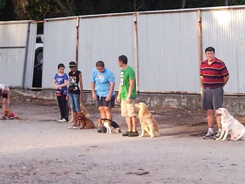
Sunday, May 11, 2008

Building Services & Refrigeration

This talk entitled “An Evening with the President of ASHRAE—Talk on ‘Building Services and Refrigeration Vital to Buildings in International Communities’” was presented by Mr. Richard H. Rooley, President 2003–2004, American Society of Heating, Refrigerating and Air-Conditioning Engineers Inc. (ASHRAE). The talk was held on Friday, 14 November 2003 at 5.30 p.m. at the IEM Conference Hall, Petaling Jaya.

Mr. Richard Rooley presenting his seminar at IEM.

Mr. Richard H. Rooley BA BAI FREng FICE FIMechE FCIBSE was educated at Morrison's Academy, Scotland and Trinity College, Dublin. He trained initially in civil, mechanical and manufacturing industries and then with the consulting practice Donald Smith Seymour and Rooley where he was partner from 1970–1991. As Principal of Project Management Partnership and Rooley Consultants since 1991, he has been associated with the design and supervision of a large number of major building engineering services projects. He has extensive experience in the cross discipline integration of design, construction and flexible space solutions in buildings. He was chairman of BSRIA from 1985–1987. In the Royal Academy of Engineering he was a Member of Council and Hon. Sec. for Civil Engineering from 1993–1995. He became President of ASHRAE in June 2003. Mr. Rooley spoke about the development of technology from the abacus to astronomy and algebra. Before the electronic calculator was invented, engineers used slide rules for calculations. Al-Khwarizmi and Sadequin were mathematicians. We were informed about the Process Change and Ages of Maintenance.


Process Change and Ages of Maintenance.

Mr. Rooley informed us of Building Demographics as follows:
– 4.7 million commercial buildings = 67.3 billion square feet
– 50% of buildings 1,001–5,000 sq. ft.
– 75% of buildings less than 10,000 sq. ft.
– approximately ¼ of workers are in buildings less than 10,000 sq. ft.

Importance
– Top 10 in importance
– Cannot live without air-conditioning and refrigeration
– The Great Enabler

Note: PCM Concrete Sdn. Bhd. recently changed name to Build Horse (M) Sdn. Bhd.

Mr. Rooley then provided some information on ASHRAE as follows.


Profile of ASHRAE.

ASHRAE Membership Profile:
85% live in North America
58% qualified to degree level

The seminar ended at 7.00 p.m.


Below are selected extracts from the handout which was given at the seminar. Most of the text from the handout has been excluded.

This Paper is based on a personal research and observations of the construction process in the United Kingdom and North America and other parts of the world. The comments in this paper are directed to the entire construction industry. The best performers in major projects have little effect on the greater majority of small projects. The owning, constructing and using buildings is constantly changing. The world of science, mathematics and engineering is also in a state of change.

In 1975 engineers were changing from slide rules to simple calculators. In the year 2000 all calculations are carried out using computers. On the assumption of increasing rate of change, the developments between 2005 and 2015 should be greater than that between slide rules and computers. This change will impact the entire construction industry. The change however from slide rule to computer around the year 2000 can be argued to be less significant than the change in 800AD when Al-Khwarizmi introduced zero to calculations.

American students who spend part of their course in Britain have problems. The American student is given an assignment and works closely with teaching staff throughout that assignment. When they visit a UK university they are usually left to their own devices to establish their methodology for the project and their own deadline. Similarly British students used to setting their own programme have difficulty in subjecting themselves to the discipline of the Americans.

The telephone, air travel, e-mail and the web have made the world smaller. Technologies, companies and people communicate across geographical, political and language barriers. As communication, including television develops, as the world's resources are used to provide a better quality of life, the users of our buildings have raised expectations. What was an acceptable condition in buildings 20 years ago is no longer accepted. These qualities are being raised worldwide. While America and Japan have been dominant with Europe becoming stronger and for a period Korea and other parts of the Pacific Group, China has now become a powerful influence. There is one manufacturer of air-conditioning equipment in Italy who encourages his principle clients to specify their exact requirements on a computer Web page. Not only does the purchaser specify in full detail, but they can purchase production time in the manufacturing facility whether in Italy or subcontracted to China. There is very little intervention by the manufacturer beyond maintenance and quality control.

In subjective discussions with firms of consultants, design contractors, architects and multi-disciplinary practices principally in America, but also in other parts of the world, it emerges that a design engineer will spend between 10 and 20% of their time on matters of strict technology as set out in the ASHRAE Handbooks, Standards and other publications. This equates to something under one day per week. The remaining four days are spent on processes of construction including negotiation and discussion with architects and other members of the design team, financial planning, special awareness, risk assessment, leadership, management and working within the team. The subjective response is also that several years are spent in learning a degree in engineering, followed by several more to achieve Charter or Professional Engineer and then continuing technical education lifelong.

The remaining four days activities are generally picked up within the office from others around. ASHRAE addresses this in courses, lectures and publications on these "soft" side of their activities.

In the USA the architect generally remains dominant in the design process. They provide leadership, they employ the consultants and sub-contractors and specify the works. The consultants are then paid by the architect out of the architect's fee. At tender stage the responsibility for the drawings which have professional engineers stamp passes to the contractor who then has the legal responsibility for performance of the completed building. In both the UK and in America there are alternatives with America moving towards partnering and in the UK projects run by the general contractor on a design and build basis. It is generally accepted that structural engineers work with great integrity. Indeed it is driven for the need for buildings never to fail. Although the same will apply to refrigeration this integrity is not a driver in air-conditioning. Most calculations are driven at the optimum performance against cost solution.

While each skill within the construction industry is very well educated, and indeed trained in that narrow field, there are great problems in communication, a fuzzy edge disease.

We continue to concentrate in university education, university courses and discussion of engineering practice on the one day per week activities. We avoid the four days per week or at best include those activities as a minor part of the curriculum. As horses were replaced by the motor car, so will our present design processes and tools be replaced, but the rate of change is much faster. Young people currently at university are being prepared for the processes of the late 20th century. Fortunately they are adaptable and may have the wisdom to adapt and lead us forward.

Selected extracts from RHR/5354
8 October 2003

Friday, May 09, 2008

Rising Podium

Construction of the podium block is underway. It isn't being built up from gridlines G/1–5 to P/1–5 level by level but instead gridlines G–J were built up first and then gridlines J–P followed from below. Maybe it's because if there should be foundation or piling problems the whole podium block will not collapse simultaneously.

Gridline G (or G1) is at the end of Block B
Gridline P is at the end of Block A
Everything in between is the Podium Block

Beam/slab formwork starting on Level 2A of the Podium Block gridlines J–P/4–5 (29 Apr 2008).

In the photo above gridlines G–J/3A–5 is already to Level 3A (back end) and gridlines G–J/1–3A is to Level 3B (front end) for the slabs.

Block B tower block progress is to Level 8 (26 Apr 2008).

The above photo was taken from the 4th floor (Level 3AA) of Block A. This back section is one and a half storeys high. The scaffolding is used as shoring for the ceiling slab. It must've been there since the 5th floor slab was cast a long time ago. It was recently removed only a few days ago. The podium slab has been cast to Level 3A (back end) and Level 3B (front end) for gridlines G–J/1–5.

Block D pilecaps (2 May 2008).

This is Block D behind the podium. The pilecaps have been concreted and at publishing time ground beams have already started. The podium slab formwork at the edge slopes downwards like a chamfer.

Block C is already to the roof level. Top floor for apartments is 3Ath floor (4th floor). Scaffolding has been erected at front of Block C for external wall plastering and casting of window hoods.

Screeding porch roof, Block C (22 Apr 2008).

This is the front of Block C. The porch roof and pergola slab are being screeded just like the floor slabs inside Block C are screeded.

Below is the podium ground slab at GL:L–M/1–3. The barbenders are finishing the slab rebar. For all ground slabs and ground beams the subgrade is compacted and then lean concrete (often abbreviated as lean con) is poured. Usually the next day the barbenders will lay the slab rebar, such as below, and then by the evening the main structural concrete will be poured. Lean con is Grade G10 MPa and structural concrete is Grade N30 for the slab. Vertical elements such as columns and shear walls are Grade N35. But shear walls from Level 16 upwards use Grade N30. The "N" means normal.

Podium ground slab at GL:L–M/1–3 (3 May 2008).

L1A Podium Slab almost ready for concreting (21 Apr 2008). It was concreted on the next day from GL:J–P/1–3A, the entire length in one go.

This photo is older than the podium photo above. The white PVC conduits will later have electrical wires pulled through them. It's for the ceiling lights for the GAth floor, the floor below this one. This entire length of podium slab was cast in one go from GL:J–P/3A–5.

The ground slab for the front portion at gridlines 1–3A GBth floor hasn't been cast yet. Lean con needs to be poured for the subgrade first. The next day the barbenders will lay the slab rebar and by evening the slab will be concreted with Grade N30. That was actually what happened.

The podium uses gridlines G, H, J, K, L, M, N and P. Gridlines I and O are not used to prevent confusion with the numbers 1 and zero.

Installing TNB transformers for the almost completed Tower A (29 Apr 2008). The yellow thing on the right is the show unit passenger hoist genset which is switched on every day to take buyers to the 8th floor.

Rain chart from 26 January 2007 to 17 April 2008. Click on chart for full size.

New Tajukon ISO requirements is that rain is now recorded as Light Rain or Heavy Rain. Adding up both will give total rain duration. This started in February 2008.

With the problems of Global Warming and disappearing ice peaks the air-con compressor was very kindly not working on 9 March. The technician who was supposed to fix it up hasn't come yet. On 27 March both fan and compressor stopped. I then sweated like a pig for a month. On 28 April I finally bought this 6 inch fan. It looks cute but it's not suited to the site conditions.

6" fan cost RM48, almost the same price for a 12" table fan.

The air-con is for display only. It doesn't work.

Reason for buying such a small fan was so I could carry it home in a bag. However it's too small and the mosquitoes aren't afraid of something so puny. So 4 days later I bought a real fan for RM53. This one's chained to the wooden wall just in case.

Philis 12 inch fan.

But it works and now I'm as cool as a cucumber :-)

Sunday, May 04, 2008

Load Bearing Walls for High-Rise Buildings

In developed Western countries such as Australia it is rare to see a single-storey or double-storey house built with an RC frame, such as we do here in Malaysia. Our old house at No. 20 is an RC frame double-storey house, and so are the neighbours' houses, and anyone who lives in a double-storey house.

I didn't look carefully at the Australian residential construction, something I now regret, but I think the double-storey houses were built with normal bricks, without the flexural reinforcement inside. As all the brick walls, both internal and external, are load bearing, this gives the building very good stability in the lateral direction. If the building only has one room inside and is supported by four external load bearing walls it would be less stable.

One of the world's tallest thin-brick bearing wall structures built in 1957, is located near Zurich, Switzerland. This 18-storey apartment structure utilizes interior load bearing brick walls of 5 to 10 inches in thickness. The exterior walls are 15-1/4 inches in thickness, the thickness in this instance being determined by the requirements for thermal insulation rather than by structural requirements. By using cavity walls, the Swiss have found a way to provide the required thermal insulation and still maintain relatively thin exterior walls.

The second photo below shows a 16-storey apartment building in Grenchen, Switzerland which utilizes cavity wall construction. The exterior walls of this building are comprised of a 6 inch brick inner bearing wythe, a 1-1/2 inch cavity and a 5 inches exterior brick wythe. The floor loads are carried by the 6 inches inner wythe and 6 inches interior brick bearing partitions. The 5 inches exterior wythe of the exterior wall is self-supporting on the foundation and is tied only at each floor level with 1/4 inches stainless steel wire anchors embedded in the edge of the slab at approximately 20 inches on centre.

Info and image source: http://www.brickinfo.org/BIA/technotes/t24.htm

From what is stated that the floor loads are carried by a 6 inches wide wythe I am assuming that the bricks are standard bricks with no flexural reinforcement inside. They are therefore bricks and not hollow precast concrete blocks which have vertical rebar, placed by the barbenders, going through the hollow centres and are later filled with concrete after block laying. This is for flexural (bending moment) strength. According to the source the load bearing brick wythe is only 1 inch thicker than the non-load bearing exterior brick veneer. "Brick veneer" means non-load bearing bricks such as the brick walls in Malaysian houses.

The benefit of using an RC frame for a bungalow house in Malaysia is that it can be extended during renovation at a later date. Lots of people do this, they buy an old bungalow house and they renovate it by adding rooms to the existing structure. This is possible if the house has a large garden, the new rooms are built by reducing the area of the garden. Brick veneer walls are then broken down to add the doors and windows.

Dr. Vagus here is building a new house for himself and his American wife and he agrees that building with blocks is much faster than using formwork for the RC frame. Over there it just isn't done like it is here.

Beam and slab formwork.

This is also beam and slab formwork. If there are beams for the slab there would usually be columns which the beams are monolithically cast to. This would be an RC structural frame and if bricks are used for the walls they are non-load bearing veneers.

The Caucasians are such good bricklayers that the brick walls are usually left unplastered. This is unlike here in Malaysia where almost all brick veneer walls are plastered. According to a Dato' relative (he wasn't a Dato' yet when he said this) the manufacturing of bricks in Malaysia is low quality, they don't come in the same size. Every brick is a different size and therefore it's impossible to build load bearing walls. It's also the reason why the walls have to be plastered here in Malaysia.

The alternative to using bricks is to use the wider hollow centred blocks as load bearing walls. However we don't do this either, we usually use an RC structural frame which is slower to build, extremely labour intensive, uses a lot of precious wood but safe for our economic conditions.

This suspended slab will be supported by columns and possibly beams unless it is a flat slab.

Sunday, April 27, 2008

Hiding The Screws

I spent Friday night reformatting my PC about 4 times because the IE was acting up. It was stopping for no reason at some websites. Photographs were partially loading without the usual red cross. I thought it was a virus but if it is a virus it's still there so I've given up. Let viruses live. I don't like my files anyway.

Not too many pics left for this Casa Indah 2 project. Block B is identical to Block A so there isn't much new. RC structure for Block C is completed or almost completed. Internal plastering, plumbing and electrical works have already started. Block B is presently at the 9th floor beam/slab formwork around Zone B.

It'd be really nice if they could fill the pool at the top of the podium block when it's completed. Block B isn't likely to be completed by then but we could have a dip during lunch. It's so hot, my room isn't air-conditioned anymore.

Ever wondered how they stick those steel angles to the columns in the carpark? If you look carefully after parking your car you'll see there are no screws but yet the parking angles stick to the column.

I thought I'd hang around and watch and here's how they do it. First they drill holes into the column. In our case it's the shear walls. The angles also have screw holes predrilled into them. Then they screw the angles to the shear wall. The welding electrode is used to weld a blob of molten electrode on top of the screw heads. This blob of electrode is allowed to cool and then it is ground flush to the shear wall angle with an electric grinder. If the angle is repainted the screw head is completely concealed. In our case the shear wall and the angles have been painted white.

Welding electrode is welded on to the top of the screw head.

The cooled blob of electrode is then ground to be flush with the angle. The screw is now hidden, only the colour gives this away. Everyone who looks at the angle thinks it is attached to the shear wall with adhesives or it is plastered there.

Here are some more pics of Block C. Block C has four floors (Ground floor to 3A) plus the roof level. The photo below shows pallets of bricks on the roof level.

Lift wall formwork on the roof of Block C (24 April 2008). This would be for the lift motor room.

Scaffolding erection starting for the internal open-air atrium of Block C (24 April 2008).

The scaffolding will allow the plasterers to perform external wall plastering and also cast the window hoods for Block C. They can cast the window sills from inside Block C but they can't cast the window hoods because the hoods are at the top of the window opening. For this they will need to be on the scaffolding outside the building.

The front of Block C looks like this.

Block C behind Block A. The TNB substation for Block A is in the foreground (25 April 2008).

Wiring the lift motor to the lift control box. The conduits are on the floor (25 April 2008).

Below is the lift control cabinet. There are many chips and PCBs inside. Wonder if it runs on Mac OS/X or Windows. I hear Mac OS/X has no viruses so it may be better to be in a lift which is controlled by Mac OS.

Lift control box. The 3 cabinets are for the 3 lift motors.

Lift motor furthest away from the lift motor room door. Don't think it's wired to the control box yet.

Below is an old photo of Block B where first floor slab formwork is being made (Level 1A and Level 1B). The gridlines for the entire block are shown. Gridlines 2A and 2B is at the right and left edges of the corridor. Unfortunately this cannot be seen for the carpark where there is no corridor. The corridor will begin from the 5th floor upwards.

Block B gridlines. Old photo taken on 7 January 2008.